XII-Physics CH-17

Alternating Current

Topic 17.1

Alternating Current and Its Characteristics

Alternating Current

Definition

An alternating current AC means a sinusoidally varying current which can be represented by time dependent sine or cosine functions.

Pioneer

Nikola Tesla (born 1856)

Contribution

He pioneered the generation, transmission and use of alternating current, which can be transmitted over much greater distances than direct current.

Output of an AC Generator

The output voltage of an AC generator is given by the following equation.
$$V=V_o\sin\omega t$$
Here $V$ is the magnitude of the alternating voltage corresponding to time $t$. Its maximum value is $V_o$ and the angular frequency of the alternating voltage is $\omega$.

For Current

$$I=I_o\sin\omega t$$
Here $I$ is the instantaneous value of the alternating current at time $t$. Its maximum or peak value is $I_o$ and its angular frequency is $\omega$.

Condition to be Alternating

A periodically varying current or voltage is termed as alternating if every cycle occupies one time period and has two symmetrical half cycles, one positive and the other negative.

Reversal

In case of current the direction of the current reverses after every half cycle, and in case of voltage the polarity of the potential difference reverses after every half cycle.

Second Condition

The amplitude or peak value of the current or voltage, that is the maximum value on both the positive and the negative sides, remains constant in all cycles.

Rate of Change

Changes occur most rapidly at the zero crossover points and most slowly at the peak.
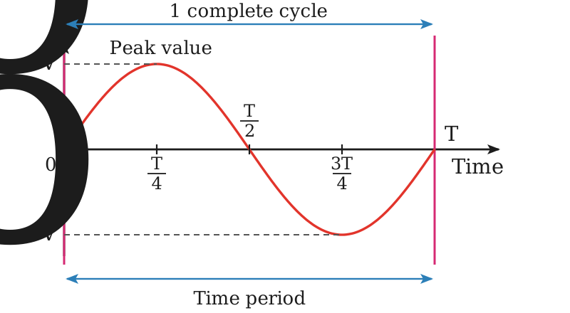
Waveform of alternating voltage

Important Terms

Definitions

Waveform is the path traced by an alternating quantity plotted as a function of time.
Cycle is one complete set of positive and negative values of an alternating quantity.
Time period $T$ is the time taken to complete one cycle and is measured in seconds.
Frequency $f$ is the number of cycles that occur in one second, measured in hertz.

Relation

$$f=\frac{1}{T}$$

Average or Mean Value

Definition

The average value of AC is obtained by averaging all instantaneous values over one half cycle.

Over a Full Cycle

The average of a complete sine wave over a full cycle from $0$ to $2\pi$ is zero, because the positive half cycle and the negative half cycle are mirror images of each other and cancel out.
$$V_{av}=0$$
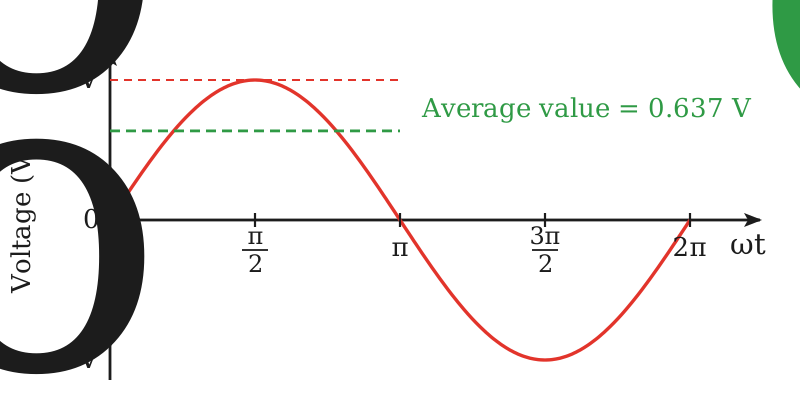
Average value of alternating voltage

Mean Values

The average value is used in situations involving rectification, where the output is a pulsating DC and it is the average of that pulsating DC which matters. For a full-wave rectified sine wave
$$I_{av}=0.637\,I_o$$
$$V_{av}=0.637\,V_o$$

Instantaneous Value

Definition

The value of an AC quantity at any instant of time is known as its instantaneous value.
$$V=V_o\sin\omega t$$

In Terms of Frequency

The angular frequency is related to the time period and the frequency as follows.
$$\omega=\frac{2\pi}{T}=2\pi f$$
So the instantaneous values can also be written as
$$V=V_o\sin(2\pi ft)$$
$$I=I_o\sin(2\pi ft)$$

Peak or Maximum Value

Definition

The peak value is the highest value that an AC waveform reaches during one cycle. It is the topmost point on the positive half cycle or the bottommost point on the negative half cycle, written as $V_o$ and $I_o$.

Peak to Peak Value

Definition

The peak to peak value is the total distance from the positive peak to the negative peak of the waveform.
$$V_{p-p}=2V_o$$

Root Mean Square Value

Definition

The rms values of current or voltage are a useful way of comparing an alternating quantity with its equivalent direct quantity. They represent the direct current or voltage that will produce the same heating effect or power dissipation as the alternating one.

Rms Current

The value of a constant current that produces the same power in a resistor as the alternating current.
$$I_{rms}=\frac{I_o}{\sqrt2}=0.707\,I_o$$

Rms Voltage

The value of a constant voltage that produces the same power in a resistor as the alternating voltage.
$$V_{rms}=\frac{V_o}{\sqrt2}=0.707\,V_o$$
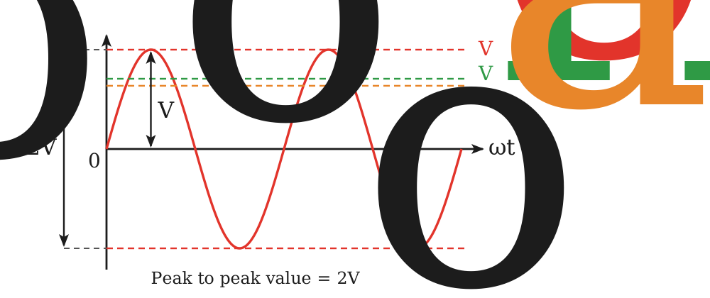
The rms value, mean value, peak value and peak-to-peak value of an alternating voltage

Short Questions

SQ 17.1.1

Why is the average value of an alternating current over a complete cycle zero?

Average Over a Full Cycle

The positive half cycle and the negative half cycle are mirror images of each other, so their instantaneous values cancel in pairs.

Result

The mean of a complete sine wave is therefore zero, and the average is taken over one half cycle instead.
$$I=I_o\sin\omega t$$
$$I_{av}=0$$
SQ 17.1.2

Why is the rms value, and not the peak value, marked on an AC supply?

Reason for Using rms

The rms value is the steady value that gives the same heating effect, so it is the value that decides the power a device takes.
$$I_{rms}=\frac{I_o}{\sqrt2}=0.707\,I_o$$

Example

A 220 V mains means an rms voltage of 220 V, whose peak value is about 311 V.
SQ 17.1.3

Find the peak value of a 220 V, 50 Hz mains supply.

Peak Value

The rms value is $0.707$ times the peak value, so
$$V_o=\frac{V_{rms}}{0.707}=\frac{220\,\mathrm{V}}{0.707}$$

Result

$$V_o=311\,\mathrm{V}$$
SQ 17.1.4

What is the time period of the 50 Hz mains, and after how long does the current reverse its direction?

Time Period

$$T=\frac{1}{f}=\frac{1}{50\,\mathrm{Hz}}=0.02\,\mathrm{s}$$

Reversal

The direction reverses after every half cycle, that is after 0.01 s, so it reverses 100 times a second.
SQ 17.1.5

State the two conditions a periodically varying current must satisfy to be called alternating.

First Condition

Every cycle must occupy one time period and have two symmetrical half cycles, one positive and the other negative.

Second Condition

The peak value on both the positive and the negative sides must remain constant in all cycles.
MCQ 17.1.1

The average value of a sinusoidal alternating voltage over one complete cycle is:

A$0.637\,V_o$B$0.707\,V_o$
CzeroD$V_o$
Solution:The two half cycles are mirror images, so they cancel over a full cycle.
MCQ 17.1.2

For a full-wave rectified sine wave the average value of the voltage is:

A$0.5\,V_o$B$0.637\,V_o$
C$0.707\,V_o$D$V_o$
Solution:The average over one half cycle is $2V_o/\pi=0.637\,V_o$.
MCQ 17.1.3

The peak to peak value of a sine wave whose rms value is 100 V is nearly:

A100 VB141 V
C200 VD283 V
Solution:Here $V_o=100/0.707=141.4\,\mathrm{V}$, and $V_{p-p}=2V_o$.
MCQ 17.1.4

The number of cycles that occur in one second is called the:

Atime periodBfrequency
CphaseDamplitude
Solution:Frequency is measured in hertz and is the reciprocal of the time period.
MCQ 17.1.5

The angular frequency of a 50 Hz alternating voltage is nearly:

A$50\,\mathrm{rad\,s^{-1}}$B$100\,\mathrm{rad\,s^{-1}}$
C$314\,\mathrm{rad\,s^{-1}}$D$628\,\mathrm{rad\,s^{-1}}$
Solution:$\omega=2\pi f=2\times3.14\times50$.
MCQ 17.1.6

The rms value of an alternating current is also known as its:

Amean valueBpeak value
Ceffective valueDinstantaneous value
Solution:It is the direct current that would give the same heating effect, so it is the effective value.
Topic 17.2

Relation Between Mean Power and Maximum Power for an Alternating Current

Statement

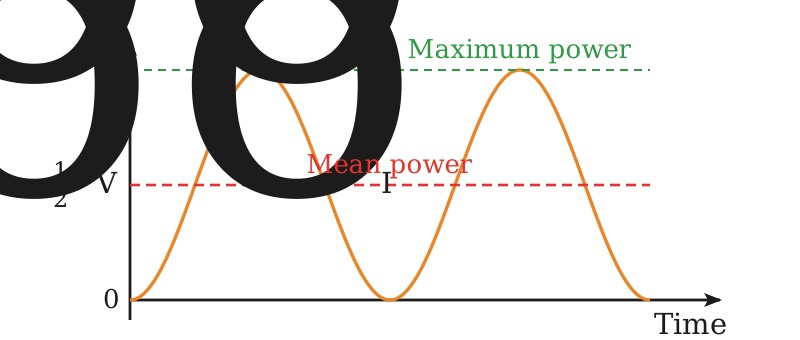
The mean power in a resistive load is half the maximum power for a sinusoidal alternating current or voltage.

Resistive Load

A resistive load is one that does not store energy, as a capacitor or an inductor does, and simply dissipates energy as heat.

Instantaneous Power

The instantaneous power $P$ in a circuit is the power at any given moment in time $t$
$$P=VI$$
Here $V$ is the instantaneous voltage and $I$ is the instantaneous current.

Maximum Power

The maximum or peak power occurs when the current and the voltage are at their peak values $I_o$ and $V_o$
$$P_{max}=I_o^2R$$

Mean Power

The mean power is the average power over one complete cycle of the AC waveform.
$$P_{mean}=I_{rms}^2R$$
Mean power is exactly half the maximum power

Derivation

The peak current is $\sqrt2$ times the rms current.
$$I_o=\sqrt2\,I_{rms}$$
Putting this in the expression for the maximum power
$$P_{max}=(\sqrt2\,I_{rms})^2R=2I_{rms}^2R$$
Substituting the mean power for $I_{rms}^2R$
$$P_{max}=2P_{mean}$$

Result

$$P_{mean}=\frac{P_{max}}{2}$$

Reason

The instantaneous power in an AC circuit varies with time. While it reaches its maximum value at certain points in the cycle, it spends a significant part of the cycle at zero or lower values, so the average works out at half the peak value.

Book Examples

Example 17.2.1

An alternating voltage supplied across a resistor of 50 $\mathrm{\Omega}$ has a voltage of 220 V. Calculate the mean power in kilowatt of the system.

Given Data

$$R=50\,\mathrm{\Omega}$$
$$V_{rms}=220\,\mathrm{V}$$

To Find

Mean power $P_{mean}=?$

Formula

$$P_{max}=\frac{V_{rms}^2}{R}$$
$$P_{mean}=\frac{P_{max}}{2}$$

Solution

Putting the values in the first relation
$$\begin{aligned}P_{max}&=\frac{(220\,\mathrm{V})^2}{50\,\mathrm{\Omega}} \\ &=968\,\mathrm{W}\end{aligned}$$
The mean power is half of the maximum power.
$$P_{mean}=\frac{968\,\mathrm{W}}{2}=484\,\mathrm{W}$$

Result

$$P_{mean}=484\,\mathrm{W}=0.484\,\mathrm{kW}$$

Short Questions

SQ 17.2.1

Why is the mean power in a resistive load half the maximum power?

Mean power in a resistor

The instantaneous power varies with time. It reaches its peak only at certain points of the cycle and spends the rest of it at zero or lower values.

Result

Averaging over one complete cycle therefore gives exactly half the peak value.
$$P_{mean}=\frac{P_{max}}{2}$$
SQ 17.2.2

A resistor dissipates a peak power of 500 W on an AC supply. Find its mean power.

Mean Power

$$P_{mean}=\frac{P_{max}}{2}=\frac{500\,\mathrm{W}}{2}$$

Result

$$P_{mean}=250\,\mathrm{W}$$
SQ 17.2.3

What is meant by a resistive load?

Resistive Load

It is a load which does not store energy, as a capacitor or an inductor does, but simply dissipates it as heat.

Examples

An electric heater, a filament lamp and an electric iron are resistive loads.
MCQ 17.2.1

For a sinusoidal alternating current in a resistive load, the ratio of the mean power to the maximum power is:

A1B$\frac{1}{2}$
C$\frac{1}{\sqrt2}$D2
Solution:$P_{max}=2P_{mean}$ follows from $I_o=\sqrt2\,I_{rms}$.
MCQ 17.2.2

The mean power dissipated in a resistive load is given by:

A$I_o^2R$B$I_{rms}^2R$
C$V_oI_o$Dzero
Solution:The mean power uses the rms current, while the peak power uses the peak current.
MCQ 17.2.3

The instantaneous power in an AC circuit is:

AconstantBvarying with time
Calways maximumDalways zero
Solution:Both $V$ and $I$ vary with time, so their product does too.
Topic 17.3

Phase of A.C.

Phase

Definition

The angle $\theta$ which specifies the instantaneous value of the alternating voltage or current is called the phase.

Instantaneous Values

$$V=V_o\sin\omega t$$
$$I=I_o\sin\omega t$$
Here the angle $\omega t$ is the phase $\theta$.

Phase of a Cycle

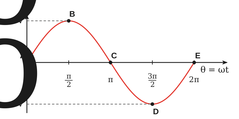
The phases of the points A, B, C, D and E of one cycle are $0,\ \pi/2,\ \pi,\ 3\pi/2$ and $2\pi$ respectively, so each point of an AC cycle corresponds to a phase.
Each point of an AC cycle corresponds to a phase

Initial Phase

The value of the phase angle $\theta$ at the instant $t$ equal to zero is called the initial phase of the AC quantity.

Phase Difference

Definition

There are situations in which the current $I$ and the voltage $V$ are not in phase, that is, they differ in phase. The angle $\phi$ between them is called the phase difference.

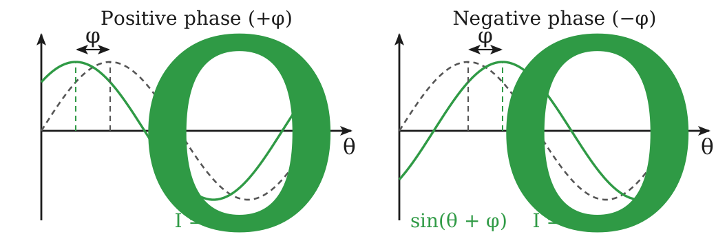
Phase Lead

Let the initial phase of the voltage be zero and the initial phase of the current be $\phi$
$$V=V_o\sin\theta$$
$$I=I_o\sin(\theta+\phi)$$
At the instant $t$ equal to zero the voltage is zero but the current is already positive.
$$I=I_o\sin\phi$$
The current had its zero value earlier by an angle $\phi$ than the voltage, so the current is leading the voltage by an angle $\phi$.

Phase Lag

Similarly, let the initial phase of the current be negative as compared with that of the voltage.
$$V=V_o\sin\theta$$
$$I=I_o\sin(\theta-\phi)$$
Here the voltage is zero but the current has some negative value, so the current will reach its zero value later by an angle $\phi$ than the voltage. The current is lagging behind the voltage by an angle $\phi$.
Current leading the voltage, and current lagging behind the voltage

Vector Representation

Conditions

An alternating quantity can be represented by an anticlockwise rotating vector if it satisfies the following conditions.
Its length on a certain scale represents the peak value or the rms value of the alternating quantity.
In the horizontal position at that instant, the alternating quantity is zero and is increasing positively.
The angular frequency of the rotating vector is the same as the angular frequency of the alternating quantity.
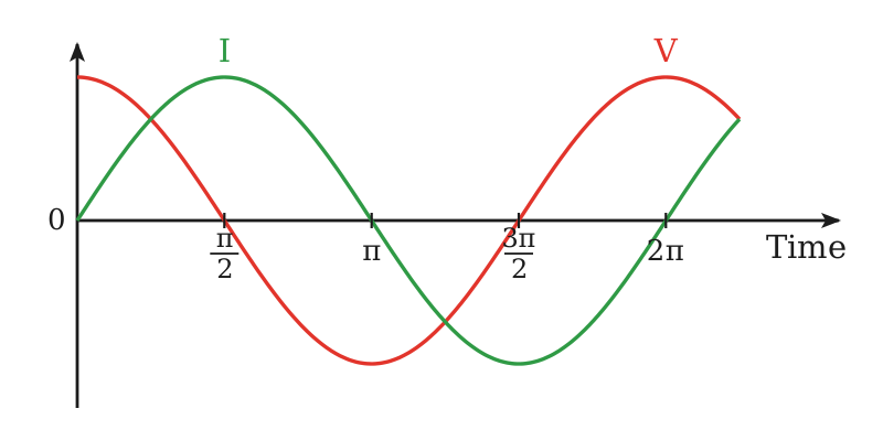
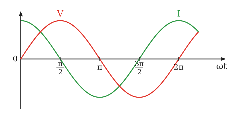
Graphical representation showing voltage V leads current I by π/2 rad

Vector Diagram

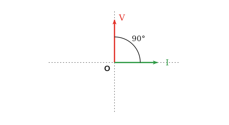
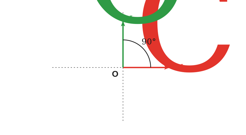
The vector OI represents the peak or rms value of the current, which is taken as the reference quantity, and OV represents the peak or rms value of the alternating voltage, which is leading the current by $\pi/2$ rad. Both vectors rotate anticlockwise with the same angular frequency.
Vector diagram OI and OV showing V leads I by π/2 rad

Short Questions

SQ 17.3.1

What is meant by the phase of an alternating quantity?

Phase

It is the angle which specifies the instantaneous value of the alternating voltage or current.
$$\theta=\omega t$$

Meaning

Each point of a cycle has its own phase, so the phase fixes where in the cycle the quantity stands.
SQ 17.3.2

For a current leading its voltage by an angle $\phi$, write the equations of the voltage and the current.

Equations

$$V=V_o\sin\theta$$
$$I=I_o\sin(\theta+\phi)$$

Reason

At the instant $t$ equal to zero the voltage is zero while the current is already $I_o\sin\phi$, so the current had its zero value earlier by an angle $\phi$.
SQ 17.3.3

When is a current said to lag behind the voltage?

Lagging Current

When the initial phase of the current is negative with respect to that of the voltage.
$$I=I_o\sin(\theta-\phi)$$

Meaning

The current reaches its zero value later by an angle $\phi$ than the voltage does.
SQ 17.3.4

State the conditions under which an alternating quantity can be represented by a rotating vector.

Conditions

Its length on a chosen scale represents the peak or the rms value of the quantity.
In the horizontal position the quantity is zero and is increasing positively.
The vector rotates anticlockwise with the same angular frequency as the quantity.
MCQ 17.3.1

The phase of the point of an AC cycle at which the quantity has its positive maximum value is:

A$0$B$\pi/2$
C$\pi$D$3\pi/2$
Solution:$\sin\theta$ is one at $\theta=\pi/2$.
MCQ 17.3.2

If the current in a circuit is $I=I_o\sin(\theta+\phi)$ while the voltage is $V=V_o\sin\theta$, then the current:

Aleads the voltage by $\phi$Blags behind the voltage by $\phi$
Cis in phase with the voltageDis zero
Solution:At $t=0$ the current is already $I_o\sin\phi$, so it reached its zero value earlier.
MCQ 17.3.3

A vector representing an alternating quantity is taken to rotate:

AclockwiseBanticlockwise
Ceither wayDit does not rotate
Solution:The convention is an anticlockwise rotation at the angular frequency of the quantity.
MCQ 17.3.4

The initial phase of an AC quantity is its phase at:

A$t=T/4$B$t=T/2$
C$t=0$D$t=T$
Solution:The initial phase is the value of $\theta$ at the instant from which time is measured.
Topic 17.4

AC Circuits

Element of a DC Circuit

The basic circuit element in a DC circuit is a resistor $R$, which controls the current or the voltage, and the relation between them is given by Ohm’s law.
$$V=IR$$

Elements of an AC Circuit

The basic circuit elements in an AC circuit are the resistor $R$, the inductor $L$ and the capacitor $C$. These elements control the current and voltage through the circuit.

What Follows

The next sections take each of these elements in turn, then the series combinations RC and RL that are built out of them.

Short Questions

SQ 17.4.1

Name the basic circuit elements of an AC circuit and say what they do.

Elements

The resistor $R$, the inductor $L$ and the capacitor $C$.

Function

They control the current and the voltage of the circuit, the resistor by resistance and the other two by reactance.
SQ 17.4.2

Which relation controls the current and the voltage of a DC circuit?

Ohm’s Law

The only basic element of a DC circuit is the resistor, and the current and voltage are related by Ohm’s law.
$$V=IR$$
MCQ 17.4.1

The basic circuit element of a DC circuit is the:

AinductorBcapacitor
CresistorDdiode
Solution:In a DC circuit the current and voltage are related by Ohm’s law through the resistance.
MCQ 17.4.2

Which one of the following is NOT a basic circuit element of an AC circuit?

AresistorBinductor
CcapacitorDdiode
Solution:The three basic elements are $R$, $L$ and $C$; a diode is a rectifying device.
Topic 17.5

AC Through a Resistor

Statement

In a purely resistive AC circuit the current and the voltage are in phase, and the opposition to the current is the resistance.

Circuit

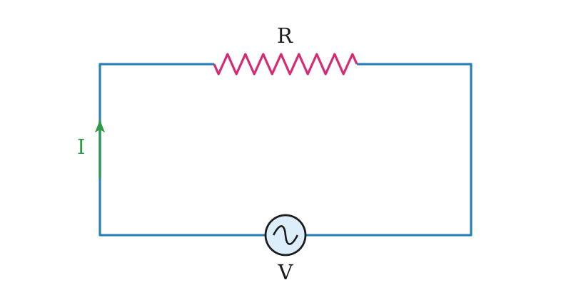
A resistor $R$ is connected with an AC source, and the instantaneous voltage is
$$V=V_o\sin\omega t$$
A resistor R connected with an AC source

Instantaneous Current

The instantaneous current through the circuit follows from Ohm’s law.
$$I=\frac{V}{R}=\frac{V_o\sin\omega t}{R}$$
$$I=I_o\sin\omega t$$

Peak Current

$$I_o=\frac{V_o}{R}$$

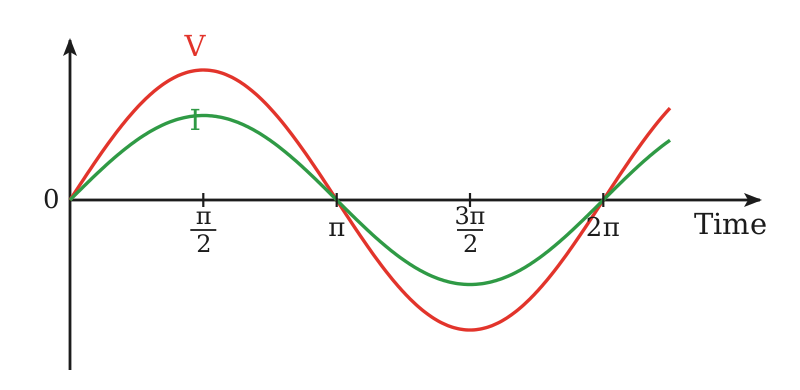
In Phase

Both the voltage and the current are sine functions of time, and both pass their minimum and maximum values at the same time, so their instantaneous values are said to be in phase with each other.
Purely resistive circuit showing V and I in phase

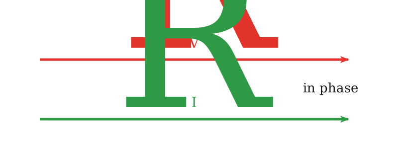
Vector Diagram

The vectors $V_R$ and $I_R$ are drawn parallel to each other because there is no phase difference between them.
V and I vectors for a resistance

Opposition to AC

The opposition to AC which the circuit presents is the resistance.
$$R=\frac{V}{I}$$

Power in a Resistor

Power Dissipation

The power dissipation is proportional to the square of the current, so it makes no difference whether the current is direct or alternating, that is, whether the sign associated with the current is positive or negative.

Comparison

The power dissipated by an AC of maximum value $I_o$ is not the same as that produced by a direct current of the same value $I_o$, because the alternating current is at its maximum value only for an instant during each half cycle.

Instantaneous Power

$$P=VI=I^2R=\frac{V^2}{R}$$

Average Power

The average of $I^2$ over one complete cycle is $I_o^2/2$, which is the same as $I_{rms}^2$, so the average power becomes
$$\langle P\rangle=\frac{I_o^2}{2}R=I_{rms}^2R$$
It can also be proved that
$$\langle P\rangle=I_{rms}V_{rms}$$

Note

Here $P$ is in watt, $V$ in volt, $I$ in ampere and $R$ in ohm, and this expression for the power holds good only when $V$ and $I$ are in phase.

Book Examples

Example 17.5.1

A 1 kW heating element is connected to a 250 V AC supply voltage. Calculate the amount of current taken from the supply and the resistance of the element when it is hot.

Given Data

$$P=1\,\mathrm{kW}=1000\,\mathrm{W}$$
$$V=250\,\mathrm{V}$$

To Find

Current $I=?$ and resistance $R=?$

Formula

$$P=VI$$
$$I=\frac{P}{V}$$
$$R=\frac{V}{I}$$

Solution

The current taken from the supply is
$$I=\frac{1000\,\mathrm{W}}{250\,\mathrm{V}}=4\,\mathrm{A}$$
The resistance of the element when hot is
$$R=\frac{250\,\mathrm{V}}{4\,\mathrm{A}}=62.5\,\mathrm{\Omega}$$

Result

$$I=4\,\mathrm{A}$$
$$R=62.5\,\mathrm{\Omega}$$

Short Questions

SQ 17.5.1

Why are the current and the voltage in phase in a purely resistive AC circuit?

Phase in a resistive circuit

The current at every instant is the voltage divided by the resistance, so it is a sine function of the same phase as the voltage.
$$I=\frac{V_o}{R}\sin\omega t$$

Result

Both pass their zero, minimum and maximum values at the same time, so there is no phase difference between them.
SQ 17.5.2

An alternating current of peak value 4 A flows through a 10 $\mathrm{\Omega}$ resistor. Find the average power dissipated.

Average Power

$$\langle P\rangle=\frac{I_o^2}{2}R=\frac{(4\,\mathrm{A})^2}{2}\times10\,\mathrm{\Omega}$$

Result

$$\langle P\rangle=80\,\mathrm{W}$$
SQ 17.5.3

Does a resistor behave differently for AC and for DC?

Behaviour

No. The power dissipation depends on the square of the current, so the sign of the current makes no difference.

Difference

An AC of peak value $I_o$ still dissipates less than a DC of the same value, because it is at its peak only for an instant in each half cycle.
MCQ 17.5.1

In a purely resistive AC circuit the phase difference between the voltage and the current is:

AzeroB$\pi/2$
C$\pi$D$\pi/4$
Solution:The current is $V/R$ at every instant, so the two are in phase.
MCQ 17.5.2

The average power in a purely resistive AC circuit is:

A$V_oI_o$B$I_{rms}V_{rms}$
CzeroD$I_o^2R$
Solution:Averaging $VI$ over a cycle gives the product of the rms values.
MCQ 17.5.3

The peak current through a resistance $R$ connected to a supply of peak voltage $V_o$ is:

A$V_{rms}/R$B$V_o/R$
C$0.707\,V_o/R$D$R/V_o$
Solution:Ohm’s law holds at every instant, so the peaks correspond.
MCQ 17.5.4

The expression $P=VI$ holds good for an AC circuit only when:

A$V$ is the peak valueB$V$ and $I$ are in phase
C$I$ is the rms valueDthe load is inductive
Solution:Otherwise a power factor $\cos\theta$ has to be included.
Topic 17.6

AC Through Inductor

LQ 2starts here — the behaviour of an inductor in an AC circuit

Inductor

Definition

An inductor, also called a coil or a choke, is a passive two terminal electrical component having a large value of self-inductance and negligible resistance, which stores energy in a magnetic field when an electric current flows through it.

Use

The inductor is used to slow down current surges or spikes by temporarily storing energy in an electromagnetic field and then releasing it back into the circuit.

AC Through an Inductor

Statement

In a pure inductor the current lags behind the voltage by $90^{\circ}$ or $\pi/2$ rad.

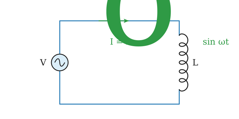
Circuit

An inductor of inductance $L$ of negligible resistance is connected with an AC source of frequency $f$, and the current is
$$I=I_o\sin\omega t$$
Inductor L connected with an AC source

Back emf

The changing current sets up a back emf in the coil of magnitude
$$V=L\frac{\Delta I}{\Delta t}$$

Applied Voltage

To maintain a constant current, the applied voltage must be equal to the back emf, so the magnitude of the applied voltage across the coil is
$$V=L\frac{\Delta}{\Delta t}(I_o\sin\omega t)$$
$$V=LI_o\frac{\Delta}{\Delta t}\sin\omega t$$

Derivation

As the rate of change of $\sin\omega t$ is $\omega\cos\omega t$, therefore
$$V=\omega LI_o\cos\omega t$$
The quantity $\omega LI_o$ is the peak voltage $V_o$, so
$$V=V_o\cos\omega t$$
A cosine is a sine shifted by a quarter cycle, that is $\cos\omega t$ equals $\sin(\omega t+\pi/2)$, therefore
$$V=V_o\sin\left(\omega t+\frac{\pi}{2}\right)$$

Phase Relation

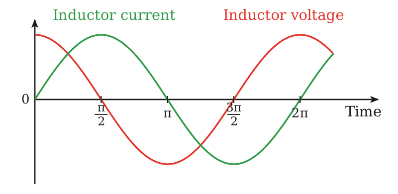
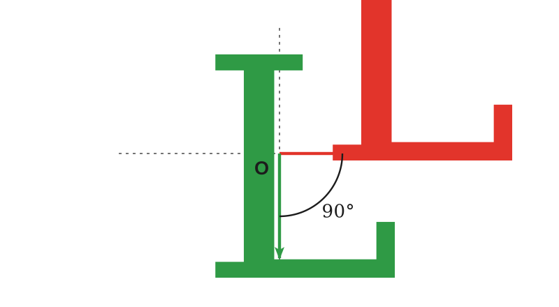
The voltage across the inductor is leading the current, or in other words the current is lagging behind the voltage. The current in an inductor always lags behind the voltage by $90^{\circ}$ or $\pi/2$ rad.
Voltage leading current in an inductor
Vector representation of V and I in an inductor

Inductive Reactance

Definition

The resistance offered by an inductor is called inductive reactance, denoted by $X_L$
$$X_L=\frac{V_{rms}}{I_{rms}}$$

In Terms of Frequency

$$X_L=\omega L=2\pi fL$$

Dependence

The inductive reactance is directly proportional to both the frequency of the current and the inductance $L$ of the inductor. The unit of $X_L$ is ohm.

For DC and AC

In case of direct current the frequency is zero, so the reactance vanishes.
$$f=0$$
$$X_L=0$$
At a large AC frequency the reactance is large instead, so an inductor allows DC but blocks AC.

Power in an Inductor

Power Dissipation

The average power dissipated in a pure inductor is zero. The inductor does not consume power, as it stores energy in the magnetic field and returns it to the source during demagnetisation.

Reason

The instantaneous power in the inductive circuit is non-zero, but the average power per cycle is zero because the phase difference between the voltage and the current is $90^{\circ}$. Since an inductor does not consume energy, it is used for controlling AC without consuming energy.
LQ 2ends here

Book Examples

Example 17.6.1

A 400 mH coil of negligible resistance is connected to an AC circuit in which a current having its rms value of 6 mA is flowing. Find out the value of rms voltage across the coil if its frequency is 1 kHz.

Given Data

$$L=400\,\mathrm{mH}=400\times10^{-3}\,\mathrm{H}$$
$$I_{rms}=6\,\mathrm{mA}=6\times10^{-3}\,\mathrm{A}$$
$$f=1\,\mathrm{kHz}=1000\,\mathrm{Hz}$$

To Find

Voltage across the coil $V_{rms}=?$

Formula

$$V_{rms}=I_{rms}X_L$$
$$X_L=2\pi fL$$
$$V_{rms}=I_{rms}(2\pi fL)$$

Solution

Putting the values in the formula
$$\begin{aligned}V_{rms}&=6\times10^{-3}\times(2\times3.14\times1000\times400\times10^{-3}) \\ &=15\,\mathrm{V}\end{aligned}$$

Result

$$V_{rms}=15\,\mathrm{V}$$

Short Questions

SQ 17.6.1

Why does an inductor allow DC but block AC?

Inductor with DC

The inductive reactance is
$$X_L=2\pi fL$$
For direct current the frequency is zero, so the reactance is zero too and the coil offers no opposition.

For AC

As the frequency rises the reactance rises with it, so a high frequency AC is blocked.
SQ 17.6.2

Find the inductive reactance of a 0.5 H coil at 50 Hz.

Inductive Reactance

$$X_L=2\pi fL=2\times3.14\times50\,\mathrm{Hz}\times0.5\,\mathrm{H}$$

Result

$$X_L=157\,\mathrm{\Omega}$$
SQ 17.6.3

Why is the average power dissipated in a pure inductor zero?

Power factor of an inductor

The phase difference between the voltage and the current is $90^{\circ}$, so the power factor $\cos\theta$ is zero.
$$P=V_{rms}I_{rms}\cos90^{\circ}$$
$$P=0$$

Energy

The inductor only stores energy in its magnetic field and returns it to the source during demagnetisation, so nothing is consumed over a cycle.
SQ 17.6.4

What sets up the back emf in an inductor carrying an alternating current?

Back emf

The changing current changes the flux through the coil, and by Faraday’s law this induces an emf in the coil itself.
$$V=L\frac{\Delta I}{\Delta t}$$
MCQ 17.6.1

The inductive reactance of a coil at zero frequency is:

AinfiniteBzero
C$2\pi L$D$L$
Solution:$X_L=2\pi fL$, which vanishes when $f=0$, so a coil passes DC freely.
MCQ 17.6.2

In a circuit containing a pure inductor the current:

Aleads the voltage by $90^{\circ}$Blags behind the voltage by $90^{\circ}$
Cis in phase with the voltageDleads the voltage by $45^{\circ}$
Solution:The applied voltage works out as $V_o\sin(\omega t+\pi/2)$ while the current is $I_o\sin\omega t$.
MCQ 17.6.3

The unit of inductive reactance is the:

AhenryBfarad
CohmDweber
Solution:It is a ratio of a voltage to a current, so it is measured in ohm like a resistance.
MCQ 17.6.4

Inductive reactance is directly proportional to:

A$1/f$B$f$
C$f^2$D$\sqrt f$
Solution:$X_L=2\pi fL$ is a first power of the frequency.
MCQ 17.6.5

An inductor is used to control an alternating current because it:

Aheats up quicklyBdoes not consume energy
Cstores chargeDblocks direct current
Solution:It stores energy in the magnetic field and returns it, so the average power in it is zero.
Topic 17.7

Choke

Definition

A choke is a coil of thick copper wire wound closely in a large number of turns over a soft iron laminated core.

Model

A choke is often modelled as a series RL-circuit, consisting of a resistor $R$ of very small resistance in series with an inductor $L$ of quite large inductance.
$$X_L=2\pi fL$$

High Inductance

The inductance of the choke coil is very high because of the high permeability of the iron core on which the coil is wound.

Power Factor

As the resistance $R$ of a choke coil is negligibly small, the power factor $\cos\theta$ of the choke coil is almost zero and the phase difference $\theta$ between the current and the voltage is nearly $90^{\circ}$. So practically no power is dissipated as heat by a choke coil.

Uses

A choke blocks high frequency AC while allowing DC and low frequency AC to pass.
Choke coils filter out high frequency AC noise from electronic circuits, ensuring a cleaner DC output.
They are essential in switch-mode power supplies, helping to regulate voltage and filter out switching noise.
They prevent unwanted radio frequency signals from leaking out of circuits, protecting other sensitive components.
Chokes in fluorescent lights generate transient voltages across the tube, making it conducive to the breakdown voltage of the gas inside.
They limit the rate of current changes in circuits, preventing damage to insulation from sudden surges.

Short Questions

SQ 17.7.1

Why is the core of a choke coil made of laminated soft iron?

Reason for Iron

Iron has a high permeability, so it makes the inductance $L$ and hence the reactance very large.

Reason for Lamination

Laminating the core cuts down the eddy currents in it, which would otherwise waste power as heat.
SQ 17.7.2

Why does a choke coil dissipate almost no power?

Power factor of a choke

Its resistance is negligibly small, so the phase difference between current and voltage is nearly $90^{\circ}$ and the power factor $\cos\theta$ is almost zero.
$$\cos\theta\approx0$$
$$P\approx0$$

Result

It limits the current without heating up, unlike a resistor.
SQ 17.7.3

Why is a choke used in a fluorescent light?

Use in a Tube Light

The choke generates a transient high voltage across the tube when the circuit is broken.

Effect

This voltage exceeds the breakdown voltage of the gas inside, so the tube strikes, and the choke then limits the running current.
MCQ 17.7.1

A choke is usually modelled as:

Aa resistance aloneBa capacitance alone
Ca very small $R$ in series with a large $L$Da large $R$ in series with a small $L$
Solution:The thick copper winding has little resistance while the iron core gives a large inductance.
MCQ 17.7.2

The power factor of a choke coil is nearly:

A1B0.7
CzeroD0.5
Solution:The phase difference is nearly $90^{\circ}$, so $\cos\theta$ is almost zero.
MCQ 17.7.3

A choke coil is used to pass:

Ahigh frequency ACBDC and low frequency AC
Cnothing at allDonly alternating current
Solution:Its reactance grows with frequency, so it blocks the high frequency components.
Topic 17.8

AC Through a Capacitor

LQ 1starts here — the behaviour of a capacitor in an AC circuit

AC Through a Capacitor

Statement

In a capacitor the current leads the voltage by $90^{\circ}$ or $\pi/2$ rad.

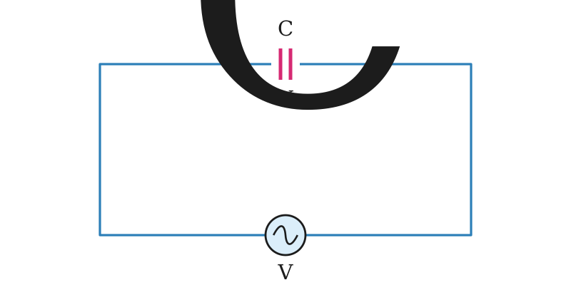
Capacitor in a Circuit

A capacitor does not allow direct current to pass through it because of the insulating medium between its plates, but alternating current can pass through a capacitor.

Reactive Component

In electric circuits a capacitor is a reactive component. Unlike a resistor it behaves differently in AC and DC circuits, because a capacitor can store energy in the form of an electric field whereas a resistor cannot store electrical energy in any form.
Capacitor connected with an AC voltage source

Working

When an alternating voltage is applied across the plates of a capacitor, it is charged in one direction and then in the other as the voltage reverses. Electrons move to and fro around the circuit connecting the plates, and this constitutes the alternating current.

Applied Voltage

$$V=V_o\sin\omega t$$

Charge on the Capacitor

The basic relation between the charge and the voltage across the plates holds good at every instant, so
$$q=CV=CV_o\sin\omega t$$

Derivation

The current is the rate of flow of charge.
$$I=\frac{\Delta q}{\Delta t}=CV_o\frac{\Delta}{\Delta t}(\sin\omega t)$$
As the rate of change of $\sin\omega t$ is $\omega\cos\omega t$, thus
$$I=\omega CV_o\cos\omega t$$
Again $\cos\omega t$ equals $\sin(\omega t+\pi/2)$, therefore
$$I=\omega CV_o\sin\left(\omega t+\frac{\pi}{2}\right)$$
The quantity $\omega CV_o$ is the peak current $I_o$, so
$$I=I_o\sin\left(\omega t+\frac{\pi}{2}\right)$$

Phase Relation

The capacitor current leads the voltage by $90^{\circ}$ or $\pi/2$ rad, or the voltage lags behind the current by the same angle.
Current and voltage for a capacitor
Vector representation of current and voltage for a capacitor

Capacitive Reactance

Definition

The resistance offered by a capacitor is known as capacitive reactance, denoted by $X_C$
$$X_C=\frac{V_{rms}}{I_{rms}}$$

In Terms of Frequency

$$X_C=\frac{1}{\omega C}=\frac{1}{2\pi fC}$$
The unit of capacitive reactance is ohm.

Effect of Frequency

For low frequencies the capacitor has a large reactance and the current is small, whereas at high frequencies the reactance is small and the current through the same capacitor is large.
LQ 1ends here

Short Questions

SQ 17.8.1

Why can an alternating current pass through a capacitor while a direct current cannot?

For DC

The insulating medium between the plates blocks a steady current, so no DC flows.
$$f=0$$
$$X_C=\infty$$

For AC

The capacitor is charged in one direction and then in the other as the voltage reverses, so electrons move to and fro in the connecting wires and this constitutes the current.
$$X_C=\frac{1}{2\pi fC}$$
SQ 17.8.2

Find the capacitive reactance of a 20 $\mathrm{\mu}$F capacitor at 50 Hz.

Capacitive Reactance

$$X_C=\frac{1}{2\pi fC}=\frac{1}{2\times3.14\times50\times20\times10^{-6}}$$

Result

$$X_C=159.2\,\mathrm{\Omega}$$
SQ 17.8.3

How does the current through a capacitor change when the frequency of the supply is raised?

Effect of Frequency

The reactance falls as the frequency rises, so the current increases.
$$X_C=\frac{1}{2\pi fC}$$

At Low Frequency

The reactance is large instead, so the current through the same capacitor is small.
SQ 17.8.4

What is the phase relation between the current and the voltage for a capacitor?

Phase Relation

The current leads the voltage by $90^{\circ}$ or $\pi/2$ rad.
$$V=V_o\sin\omega t$$
$$I=I_o\sin\left(\omega t+\frac{\pi}{2}\right)$$
MCQ 17.8.1

In a circuit containing a pure capacitor the current:

Aleads the voltage by $90^{\circ}$Blags behind the voltage by $90^{\circ}$
Cis in phase with the voltageDis zero
Solution:Differentiating $q=CV_o\sin\omega t$ gives $I=I_o\sin(\omega t+\pi/2)$.
MCQ 17.8.2

Capacitive reactance is inversely proportional to:

Athe capacitance onlyBthe frequency only
Cboth the frequency and the capacitanceDneither of them
Solution:$X_C=1/2\pi fC$ carries both in its denominator.
MCQ 17.8.3

The peak current through a capacitor connected to a supply of peak voltage $V_o$ is:

A$V_o/\omega C$B$\omega CV_o$
C$\omega C^2V_o$D$CV_o$
Solution:$I_o=V_o/X_C$ and $X_C=1/\omega C$.
MCQ 17.8.4

At a very high frequency a capacitor behaves as:

Aan open circuitBa short circuit
Ca pure resistanceDan inductor
Solution:Its reactance $1/2\pi fC$ becomes very small, so it offers almost no opposition.
MCQ 17.8.5

A capacitor stores energy in the form of:

Aa magnetic fieldBan electric field
CheatDlight
Solution:This is why it is a reactive component and dissipates no power, unlike a resistor.
Topic 17.9

Impedance

Definition

The combined effect of resistance and reactance in an AC circuit is known as impedance.

Opposition in an AC Circuit

In AC circuits the opposition to current flow is called impedance, denoted by $Z$, which includes both resistance $R$ and reactance $X$.

Resistance and Reactance

The resistance $R$ is the opposition to current flow due to resistors, while reactance is the opposition to current flow due to capacitors and inductors, that is $X_C$ and $X_L$. A pure resistive circuit has only resistance and no reactance.

Mathematical Form

It is the ratio of the rms value of the voltage to the rms value of the current.
$$Z=\frac{V_{rms}}{I_{rms}}$$

SI Unit

$$\mathrm{\Omega}$$

Book Examples

Example 17.9.1

An AC circuit operates by a peak voltage of 200 V and 10 A as peak input current. Find the impedance of the circuit.

Given Data

$$V_o=200\,\mathrm{V}$$
$$I_o=10\,\mathrm{A}$$

To Find

Impedance $Z=?$

Formula

$$V_{rms}=0.707\,V_o$$
$$I_{rms}=0.707\,I_o$$
$$Z=\frac{V_{rms}}{I_{rms}}$$

Solution

The rms values of the voltage and the current are
$$V_{rms}=200\,\mathrm{V}\times0.707=141.4\,\mathrm{V}$$
$$I_{rms}=10\,\mathrm{A}\times0.707=7.07\,\mathrm{A}$$
Putting these in the impedance relation
$$Z=\frac{141.4\,\mathrm{V}}{7.07\,\mathrm{A}}=20\,\mathrm{\Omega}$$

Result

$$Z=20\,\mathrm{\Omega}$$

Short Questions

SQ 17.9.1

What is impedance, and how does it differ from resistance?

Impedance

It is the combined effect of resistance and reactance in an AC circuit, that is the ratio of the rms voltage to the rms current.
$$Z=\frac{V_{rms}}{I_{rms}}$$

Difference

Resistance is the opposition due to resistors alone, while impedance also includes the reactance of inductors and capacitors.
SQ 17.9.2

An AC circuit takes 5 A rms from a 100 V rms supply. Find its impedance.

Impedance

$$Z=\frac{V_{rms}}{I_{rms}}=\frac{100\,\mathrm{V}}{5\,\mathrm{A}}$$

Result

$$Z=20\,\mathrm{\Omega}$$
MCQ 17.9.1

Impedance is the combined effect of:

Aresistance onlyBreactance only
Cresistance and reactanceDinductance and capacitance only
Solution:$Z$ takes in the resistance of resistors and the reactance of inductors and capacitors.
MCQ 17.9.2

The SI unit of impedance is the:

AhenryBfarad
CohmDvolt
Solution:It is the ratio of the rms voltage to the rms current.
MCQ 17.9.3

A purely resistive AC circuit has:

Areactance but no resistanceBresistance but no reactance
Cinfinite impedanceDzero impedance
Solution:Reactance comes only from inductors and capacitors, which such a circuit does not have.
Topic 17.10

AC Through RC-Series Circuit

LQ 3starts here — the impedance of an RC-series circuit, and runs on into the RL-series circuit

Statement

In an RC-series circuit the applied voltage is the vector sum of $V_R$ and $V_C$, and the current leads the applied voltage by the phase angle $\theta$.

Circuit

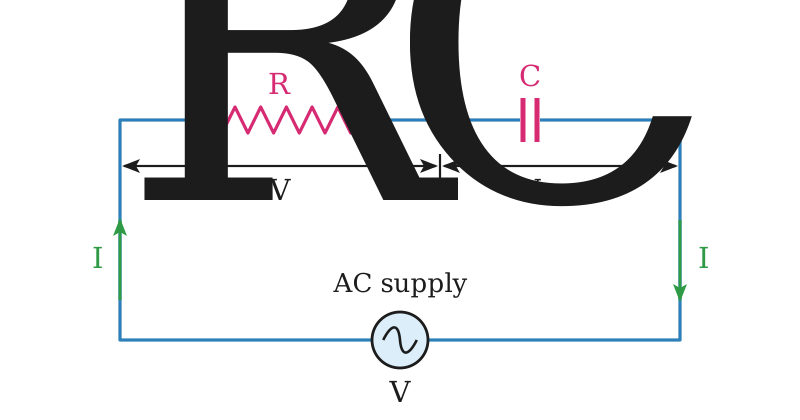
A resistance $R$ and a capacitor $C$ are connected in series with an alternating voltage source. As $R$ and $C$ are in series, the same current flows through each of them.
Resistor and capacitor connected in series with an AC voltage source

Voltage Across R

The potential difference across the resistance is in phase with the current, so it is represented by a line along the current line.
$$V_R=I_{rms}R$$

Voltage Across C

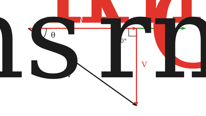
The potential difference across the capacitor lags behind the current by $\pi/2$ rad, so the line representing it is drawn at right angles to the current line.
$$V_C=I_{rms}X_C=\frac{I_{rms}}{\omega C}$$
Vector diagram showing the relationship of I with VC and VR

Applied Voltage

The applied voltage that will send the current through the circuit is obtained as the resultant of these two vectors.
$$V_{rms}=\sqrt{(V_R)^2+(V_C)^2}$$
$$V_{rms}=\sqrt{(I_{rms}R)^2+\left(\frac{I_{rms}}{\omega C}\right)^2}$$
$$V_{rms}=I_{rms}\sqrt{R^2+\left(\frac{1}{\omega C}\right)^2}$$

Impedance

$$Z=\sqrt{R^2+\left(\frac{1}{\omega C}\right)^2}$$

Vector Addition

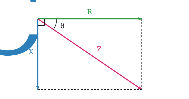
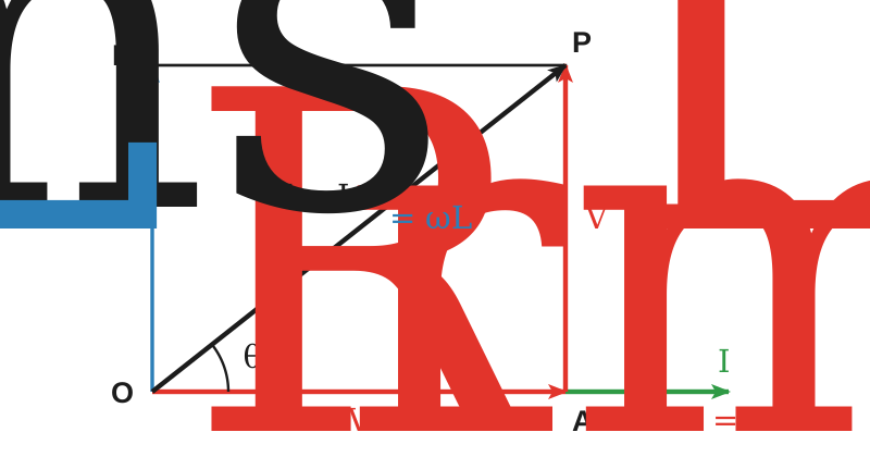
The impedance of a series AC circuit can therefore be found by vector addition. The resistance is drawn as a horizontal line in the direction of the current, the capacitive reactance as a line lagging the R-line by $90^{\circ}$, and the impedance as their vector sum.
Impedance diagram of an RC-series circuit

Phase Angle

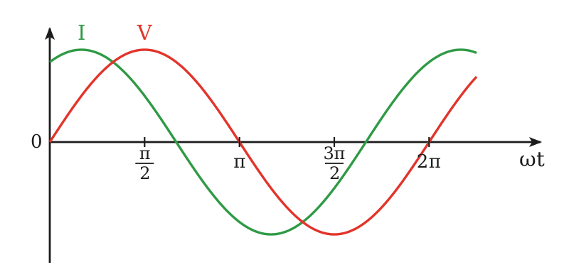
The angle which the impedance line makes with the R-line gives the phase difference between the voltage and the current, and in this circuit the current leads the applied voltage.
$$\theta=\tan^{-1}\left(\frac{X_C}{R}\right)=\tan^{-1}\left(\frac{1}{\omega CR}\right)=\tan^{-1}\left(\frac{1}{2\pi fCR}\right)$$
Voltage and current waveform in an RC-series circuit

Power Consumed

The power consumed in an RC-series circuit is primarily due to the resistor, as the capacitor only stores energy and does not dissipate it.
$$P=I^2R=VI\cos\theta$$

Book Examples

Example 17.10.1

A resistor of resistance 5 k$\mathrm{\Omega}$ is connected in series with a capacitor of capacitance 5 $\mathrm{\mu}$F across the AC source of 220 V that has frequency 50 Hz. Calculate the phase angle.

Given Data

$$R=5\,\mathrm{k\Omega}=5000\,\mathrm{\Omega}$$
$$C=5\,\mathrm{\mu F}=5\times10^{-6}\,\mathrm{F}$$
$$f=50\,\mathrm{Hz}$$

To Find

Phase angle $\theta=?$

Formula

$$\theta=\tan^{-1}\left(\frac{1}{\omega CR}\right)$$
Putting $2\pi f$ for $\omega$
$$\theta=\tan^{-1}\left(\frac{1}{2\pi fCR}\right)$$

Solution

Putting the values in the formula
$$\begin{aligned}\theta \\ &=\tan^{-1}\left(\frac{1}{2\times3.14\times50\times5\times10^{-6}\times5000}\right)\end{aligned}$$
$$\theta=\tan^{-1}(0.1273)=7.25^{\circ}$$

Result

$$\theta=7.25^{\circ}$$

Short Questions

SQ 17.10.1

Why is the impedance of an RC-series circuit found by vector addition rather than by simple addition?

Phase difference in an RC circuit

The voltage across $R$ is in phase with the current while the voltage across $C$ lags it by $90^{\circ}$, so the two are not in the same direction.

Result

They add as vectors at right angles.
$$Z=\sqrt{R^2+X_C^2}$$
SQ 17.10.2

Find the impedance of a 30 $\mathrm{\Omega}$ resistance in series with a capacitive reactance of 40 $\mathrm{\Omega}$.

Impedance

$$Z=\sqrt{R^2+X_C^2}=\sqrt{(30)^2+(40)^2}$$

Result

$$Z=50\,\mathrm{\Omega}$$
SQ 17.10.3

In an RC-series circuit, which element consumes the power and why?

Element

Only the resistor consumes power.

Reason

The capacitor stores energy in its electric field and returns it to the source, so it dissipates nothing.
$$P=I^2R=VI\cos\theta$$
MCQ 17.10.1

In an RC-series circuit the current:

Alags behind the applied voltageBleads the applied voltage
Cis in phase with itDis zero
Solution:The capacitor voltage lags the current, so the resultant applied voltage lags it too.
MCQ 17.10.2

The impedance of an RC-series circuit is:

A$R+X_C$B$\sqrt{R^2+X_C^2}$
C$R-X_C$D$RX_C$
Solution:The two voltages are at right angles, so they add as vectors.
MCQ 17.10.3

The phase angle of an RC-series circuit is the inverse tangent of:

A$R/X_C$B$X_C/R$
C$RX_C$D$1/RX_C$
Solution:It is the angle the impedance line makes with the R-line of the impedance diagram.
MCQ 17.10.4

The power consumed in an RC-series circuit is:

A$VI$B$VI\cos\theta$
C$VI\sin\theta$Dzero
Solution:Only the resistor dissipates power, and $I^2R$ can be written as $VI\cos\theta$.
Topic 17.11

AC Through RL-Series Circuit

Statement

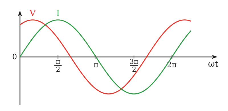
In an RL-series circuit the applied voltage is the vector sum of $V_R$ and $V_L$, and it leads the current by the phase angle $\theta$.

Circuit

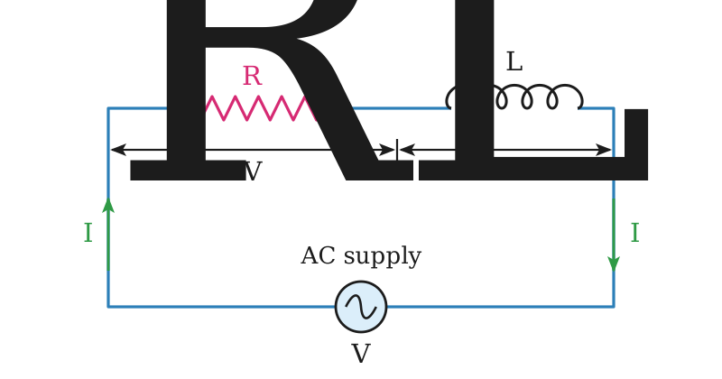
A resistor $R$ and an inductor $L$ are connected in series with an AC source. As $R$ and $L$ are in series, the same current $I$ flows through both of them.
$$I=I_o\sin\theta$$
RL-series circuit connected with AC supply

Voltage Across R

The rms voltage across $R$ is in phase with the current in the circuit.
$$V_R=I_{rms}R$$

Voltage Across L

The voltage across $L$ leads the current through $L$ by $\pi/2$ rad.
$$V_L=I_{rms}X_L$$
Voltage and current waveform in an RL-series circuit
Vector diagram of VR and VL in an RL-series circuit

Resultant Voltage

The resultant voltage is the vector sum of the two.
$$V_{rms}=\sqrt{V_R^2+V_L^2}$$
$$V_{rms}=\sqrt{(I_{rms}R)^2+(I_{rms}X_L)^2}$$
The inductive reactance is $\omega L$, therefore
$$V_{rms}=I_{rms}\sqrt{R^2+(\omega L)^2}$$

Impedance

$$Z=\sqrt{R^2+(\omega L)^2}$$

Phase Angle

The angle which $Z$ makes with the R-line gives the phase difference between the applied voltage and the current.
$$\theta=\tan^{-1}\left(\frac{\omega L}{R}\right)$$

Power in an RL Circuit

Power Dissipation

The power consumed is primarily due to the resistor, as the inductor stores energy but ideally does not dissipate it.
$$P=I^2R=VI\cos\theta$$

Power Factor

The factor $\cos\theta$ is known as the power factor.

Inverter Efficiency

When DC power is converted into AC power, a quantity known as inverter efficiency has to be taken into account. It is usually 85% to 90%.
$$P_{ac}=(\text{inverter efficiency})\times P_{dc}$$
LQ 3ends here

Short Questions

SQ 17.11.1

Find the impedance of a coil of reactance 8 $\mathrm{\Omega}$ in series with a resistance of 6 $\mathrm{\Omega}$.

Impedance

$$Z=\sqrt{R^2+X_L^2}=\sqrt{(6)^2+(8)^2}$$

Result

$$Z=10\,\mathrm{\Omega}$$
SQ 17.11.2

What is meant by the power factor of an RL-series circuit?

Power Factor

It is the factor $\cos\theta$ in the power expression, where $\theta$ is the phase angle between the applied voltage and the current.
$$P=VI\cos\theta$$

Meaning

It tells what fraction of the apparent power is actually consumed, and it is one for a pure resistance and zero for a pure inductance.
SQ 17.11.3

A solar panel supplies 500 W of DC power to an inverter of 80% efficiency. Find the AC power obtained.

AC Power

$$P_{ac}=(\text{inverter efficiency})\times P_{dc}=0.80\times500\,\mathrm{W}$$

Result

$$P_{ac}=400\,\mathrm{W}$$
MCQ 17.11.1

In an RL-series circuit the current:

Alags behind the applied voltageBleads the applied voltage
Cis in phase with itDis zero
Solution:The voltage across the inductor leads the current, so the resultant voltage leads it as well.
MCQ 17.11.2

The impedance of an RL-series circuit is:

A$R+\omega L$B$\sqrt{R^2+(\omega L)^2}$
C$R-\omega L$D$\omega L/R$
Solution:$V_R$ and $V_L$ are at right angles, so their resultant gives this impedance.
MCQ 17.11.3

The power factor of an AC circuit is:

A$\sin\theta$B$\cos\theta$
C$\tan\theta$D$\cot\theta$
Solution:It is the factor by which the apparent power is multiplied to give the power consumed.
MCQ 17.11.4

The efficiency of an inverter converting DC power into AC power usually lies between:

A50% and 60%B70% and 75%
C85% and 90%Dexactly 100%
Solution:Some energy is always lost in the switching and the transformer of the inverter.
Topic 17.12

Rectification

LQ 4starts here — full-wave rectification and the bridge rectifier

Rectification

Definition

Rectification is the process of converting alternating current into direct current.

Diode

Diodes allow current to flow in one direction, that is when forward biased, but block it in the opposite direction when reverse biased.

Types

Rectification is of two types, half-wave rectification and full-wave rectification. It is commonly used in electronic devices that require a stable DC power source, such as computers and smartphones, as most household and commercial power is AC.

Diode as a Rectifier

A diode allows a large current to flow when forward biased, while the current through a reverse biased diode is practically zero. It is due to this property that a diode can be used for rectification.

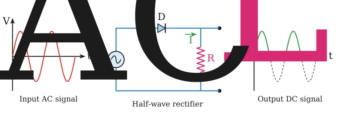
Half-Wave Rectifier

Definition

In half-wave rectification an AC signal is converted into pulsating direct current by passing one half cycle of the waveform and blocking the other half.
Working of a half-wave rectifier, showing graphically its input and output waveforms

Working

An alternating voltage of period $T$ is supplied to a diode D connected in series with a load resistance $R_L$. During the positive half cycle, in the interval $0\to T/2$, the diode is forward biased, so it offers a very low resistance and current flows through $R_L$.

Negative Half Cycle

During the interval $T/2\to T$ the diode becomes reverse biased and offers a very high resistance, so practically no current flows through $R_L$. The same events repeat during the next cycle.

Output

The current across $R_L$ flows in only one direction, which means it is direct current, but this current flows in pulses.

Full-Wave Rectification

Definition

Rectification during which both halves of the alternating input voltage are converted into unidirectional current through a resistance is called full-wave rectification.

Bridge Rectifier

Definition

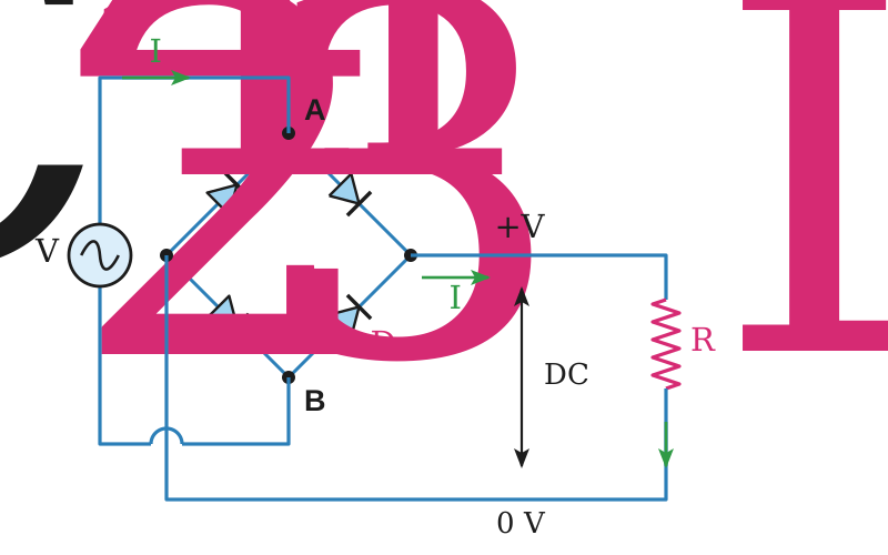
Full-wave rectification is achieved by a bridge rectifier in which four individual rectifying diodes are connected in a closed loop bridge configuration. The single secondary winding is connected to one side of the diode bridge network and the load to the other side. The four diodes are arranged in series pairs, with only two diodes conducting during each half cycle.
Full-wave bridge rectifier circuit showing the four diode network with load resistance

The Positive Half Cycle

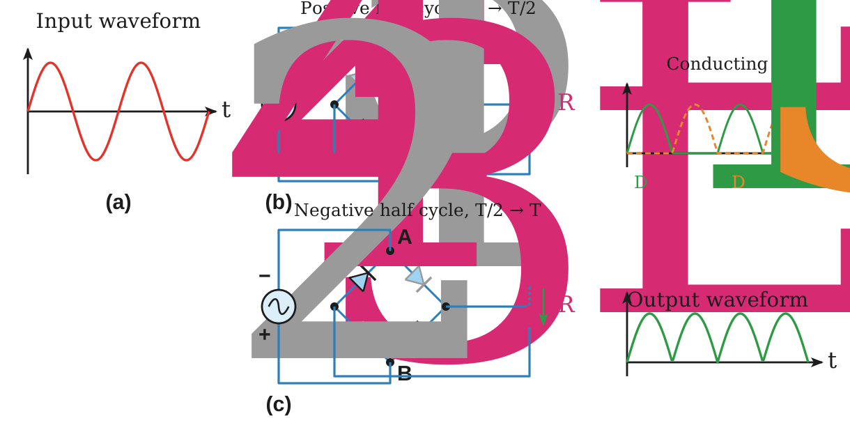
During the time $0\to T/2$ the terminal A of the bridge is positive with respect to the terminal B. The diodes D1 and D2 become forward biased and conduct in series, while D3 and D4 are reverse biased, and the current flows through the load resistance.

The Negative Half Cycle

During the time $T/2\to T$ the terminal A is negative and B is positive. Now D3 and D4 conduct in series while D1 and D2 switch off, as they are reverse biased. The current through the load is in the same direction as before.
The bridge rectifier during its positive and negative half cycles, with its input and output waveforms

Conclusion

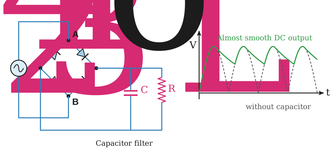
Both halves of the alternating input voltage send a unidirectional current through the load resistance. The output voltage is not smooth but pulsating, and it can be made smooth using a circuit called a filter, which may consist of capacitors, inductors and resistors.

Smoothing Capacitor

Definition

Smoothing filters are used to reduce the ripple voltage after rectification. In a capacitor filter a capacitor is connected in parallel with the load. It charges when the rectified voltage increases and discharges when the voltage decreases, thereby smoothing the output.

Effect

A reservoir capacitor connected in parallel with the load increases the average DC output level even higher, as the capacitor acts like a storage device, and converts the full-wave rippled output into a more smooth DC output voltage.
The smoothing capacitor converts the full-wave rippled output of the rectifier into a more smooth DC output voltage

Ripple Voltage

The maximum ripple voltage in a full-wave bridge circuit is not determined by the value of the smoothing capacitor but by the frequency and the load current.
$$V_{ripple}=\frac{I_{DC}}{f_{ripple}C}=\frac{I_{DC}}{2fC}$$
Here $I_{DC}$ is the load current in ampere, $f$ is the input frequency and $C$ is the capacitance in farad.

Ripple Frequency

The ripple frequency is twice that of the input frequency.
$$f_{ripple}=2f$$
LQ 4ends here

Short Questions

SQ 17.12.1

What is rectification, and which property of a diode makes it possible?

Rectification

It is the process of converting alternating current into direct current.

Property of a Diode

A diode passes a large current when forward biased and practically none when reverse biased, so it lets the current through in one direction only.
SQ 17.12.2

Why does a half-wave rectifier waste half of the input?

Only one half cycle used

The single diode is forward biased only during the positive half cycle. During the negative half cycle it is reverse biased and offers a very high resistance, so practically no current flows through the load.

Result

Only one half of each cycle reaches the load, and the output is a pulsating DC.
SQ 17.12.3

How many diodes conduct during each half cycle of a bridge rectifier, and which ones?

Conducting Diodes

Two diodes conduct in series during each half cycle.

Which Ones

D1 and D2 conduct during the positive half cycle, while D3 and D4 conduct during the negative half cycle, and the load current keeps the same direction in both.
SQ 17.12.4

A full-wave rectifier is fed from a 50 Hz supply. Find its ripple frequency.

Ripple Frequency

The ripple frequency of a full-wave rectifier is twice the input frequency.
$$f_{ripple}=2f=2\times50\,\mathrm{Hz}$$

Result

$$f_{ripple}=100\,\mathrm{Hz}$$
SQ 17.12.5

How does a smoothing capacitor reduce the ripple in a rectifier output?

Working

The capacitor is connected in parallel with the load. It charges when the rectified voltage rises and discharges into the load when the voltage falls.

Effect

The load therefore never sees the full dip between the pulses, so the average DC level rises and the output becomes much smoother.
MCQ 17.12.1

In a half-wave rectifier the diode conducts for:

Athe whole cycleBone half of the cycle
Ca quarter of the cycleDnone of the cycle
Solution:It is forward biased in the positive half cycle and reverse biased in the negative one.
MCQ 17.12.2

A full-wave bridge rectifier uses:

Aone diodeBtwo diodes
Cthree diodesDfour diodes
Solution:The four diodes are arranged in series pairs in a closed loop bridge.
MCQ 17.12.3

During the positive half cycle of a bridge rectifier the conducting diodes are:

AD1 and D2BD3 and D4
CD1 and D3Dall four
Solution:Terminal A is then positive, so D1 and D2 are forward biased while D3 and D4 are reverse biased.
MCQ 17.12.4

The ripple frequency of a full-wave rectifier working on a 50 Hz supply is:

A25 HzB50 Hz
C100 HzD200 Hz
Solution:Both half cycles produce a pulse, so $f_{ripple}=2f$.
MCQ 17.12.5

In a capacitor filter the smoothing capacitor is connected:

Ain series with the loadBin parallel with the load
Cin series with one diodeDin place of the load
Solution:It charges on the rising voltage and discharges into the load on the falling voltage.
MCQ 17.12.6

The output of a rectifier before filtering is:

Apure DCBalternating current
Cpulsating DCDzero
Solution:The current keeps one direction but rises and falls, so a filter is needed to smooth it.
Topic 17.13

Self-Induction

LQ 5starts here — self-induction and the expression for self-inductance

Self-Induction

Definition

The phenomenon, in which a changing current induces an emf inside the coil itself, is called self-induction.

Experiment

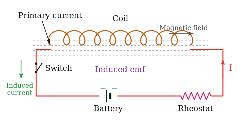
A coil is connected in series with a battery, a switch and a rheostat. If the rheostat is moved quickly, the current through the coil changes, the magnetic flux through the coil also changes, and this finally induces an emf in the coil itself.
A coil showing production of induced current and induced emf in itself

Self-Inductance

Definition

The self-inductance of a coil is the ratio of the emf induced in it to the rate of change of current through it.

Flux Linkage

Let $\phi$ be the flux passing through one loop of a coil of $N$ turns, so the flux passing through the coil is $N\phi$. As this flux is proportional to the magnetic field produced, which is in turn proportional to the current, therefore
$$N\phi\propto I$$
$$N\phi=LI$$
Here $L$ is the proportionality constant, called the self-inductance of the coil.

Depending Factors

Number of turns of the coil.
Area of cross-section of the coil.
Core material. Winding the coil around a ferromagnetic iron core increases the magnetic flux, and hence the inductance, significantly relative to an air core.

Induced emf

By Faraday’s law the emf induced in the coil is
$$\varepsilon_L=-N\frac{\Delta\phi}{\Delta t}=-\frac{\Delta(N\phi)}{\Delta t}$$
Using the flux linkage
$$\varepsilon_L=-\frac{\Delta(LI)}{\Delta t}$$
$$\varepsilon_L=-L\frac{\Delta I}{\Delta t}$$

Expression

$$L=\frac{\varepsilon_L}{\dfrac{\Delta I}{\Delta t}}$$
The minus sign indicates that the induced emf opposes the applied voltage.

Henry

If the emf induced in the coil is 1 V when the current flowing through it changes at the rate of $1\,\mathrm{A\,s^{-1}}$, the coil has a self-inductance of 1 henry.

SI Unit

$$\mathrm{V\,s\,A^{-1}}$$

Another Form

Equating the two expressions for the induced emf
$$-N\frac{\Delta\phi}{\Delta t}=-L\frac{\Delta I}{\Delta t}$$
$$L=N\frac{\Delta\phi}{\Delta I}$$

Energy Stored in an Inductor

Statement

The energy stored in an inductor is half the product of its inductance and the square of the current through it.

Set Up

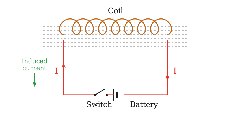
When the switch is turned on, the current increases from zero to its maximum value. Due to the change of current an emf is induced which opposes that of the battery, so work is done by the battery to move charges against the induced emf.
Circuit designed to calculate energy stored in an inductor

Work Done

The work done by the battery in moving a small charge $\Delta q$ is
$$W=\Delta q\,\varepsilon_L=\Delta q\,L\frac{\Delta I}{\Delta t}=\frac{\Delta q}{\Delta t}L\Delta I$$

Average Current

Here $\Delta q/\Delta t$ is the average current, and the current rises from zero to $I$
$$\Delta I=I-0=I$$
$$\frac{\Delta q}{\Delta t}=\frac{0+I}{2}=\frac{1}{2}I$$

Result

$$W=\frac{1}{2}LI^2$$

Energy Stored

This work is stored as potential energy in the inductor.
$$U_m=\frac{1}{2}LI^2$$

Note

In an inductor the energy is stored in the magnetic field and can never be negative, because it is proportional to the square of the current. The inductor stores energy while absorbing power and returns it when delivering power, so the net energy transfer can never be negative.

In Terms of the Magnetic Field

For a solenoid of $n$ turns per unit length, area of cross-section $A$ and length $l$
$$B=\mu_o nI$$
$$I=\frac{B}{\mu_o n}$$
$$L=\mu_o n^2Al$$
Substituting these values
$$U_m=\frac{1}{2}\mu_o n^2Al\left(\frac{B}{\mu_o n}\right)^2=\frac{B^2}{2\mu_o}(Al)$$
As $Al$ is the volume of the solenoid
$$\frac{U_m}{\text{volume}}=\frac{B^2}{2\mu_o}$$

Energy Density

The energy stored per unit volume inside the solenoid is called the energy density.
$$\text{Energy density}=\frac{B^2}{2\mu_o}$$
LQ 5ends here

Short Questions

SQ 17.13.1

On what factors does the self-inductance of a coil depend?

Depending Factors

The number of turns of the coil.
The area of cross-section of the coil.
The core material, an iron core raising the flux and hence the inductance far above that of an air core.
$$L=\frac{\mu_o\mu_r N^2A}{l}$$
SQ 17.13.2

Find the emf induced in a coil of self-inductance 2 H when the current through it changes at 5 A s$^{-1}$.

Induced emf

$$\varepsilon_L=L\frac{\Delta I}{\Delta t}=2\,\mathrm{H}\times5\,\mathrm{A\,s^{-1}}$$

Result

$$\varepsilon_L=10\,\mathrm{V}$$
SQ 17.13.3

Why can the energy stored in an inductor never be negative?

Energy stored in an inductor

The energy depends on the square of the current, so it is positive whichever way the current flows.
$$U_m=\frac{1}{2}LI^2$$

Energy Transfer

The inductor stores energy while absorbing power and returns only what it stored, so the net transfer can never be negative.
SQ 17.13.4

A coil of self-inductance 0.4 H carries a current of 3 A. Find the energy stored in it.

Energy Stored

$$U_m=\frac{1}{2}LI^2=\frac{1}{2}\times0.4\,\mathrm{H}\times(3\,\mathrm{A})^2$$

Result

$$U_m=1.8\,\mathrm{J}$$
MCQ 17.13.1

The self-inductance of a coil is increased the most by:

Areducing the number of turnsBwinding it on a ferromagnetic iron core
Creducing its area of cross-sectionDshortening the coil
Solution:The high permeability of iron raises the flux, and hence the inductance, far above that of an air core.
MCQ 17.13.2

One henry is equal to:

A$1\,\mathrm{V\,A^{-1}}$B$1\,\mathrm{V\,s\,A^{-1}}$
C$1\,\mathrm{A\,s\,V^{-1}}$D$1\,\mathrm{Wb\,A^{-2}}$
Solution:An emf of one volt for a current changing at one ampere per second is one henry.
MCQ 17.13.3

The energy stored in an inductor carrying a current $I$ is:

A$LI$B$\frac{1}{2}LI^2$
C$LI^2$D$\frac{1}{2}L^2I$
Solution:It is the work done by the source against the induced emf while the current grows from zero to $I$.
MCQ 17.13.4

The energy density inside a current carrying solenoid is:

A$B^2/\mu_o$B$B^2/2\mu_o$
C$2B^2/\mu_o$D$\mu_oB^2/2$
Solution:Dividing $U_m=B^2(Al)/2\mu_o$ by the volume $Al$ leaves $B^2/2\mu_o$.
MCQ 17.13.5

The minus sign in $\varepsilon_L=-L\,\Delta I/\Delta t$ shows that the induced emf:

Aaids the applied voltageBopposes the applied voltage
Cis always zeroDis constant in time
Solution:This is Lenz’s law, which is why the induced emf is called a back emf.
Topic 17.14

Mutual Induction

LQ 6starts here — mutual inductance, its relation and the definition of henry

Mutual Induction

Definition

The phenomenon in which a changing current in one coil induces an emf in another coil is called mutual induction.

Experiment

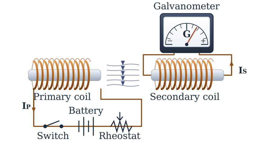
Two coils are placed close to each other. One coil, connected with a battery through a switch and a rheostat, is called the primary coil, and the other, connected to a galvanometer, is called the secondary coil.
Circuit diagram to find mutual induction between two coils

Working

If the current in the primary is changed by varying the resistance of the rheostat, the magnetic flux in the surrounding region changes. Since the secondary coil is in the magnetic field of the primary, the changing flux also links with the secondary, and this causes an induced emf in the secondary.

Mutual Inductance

Definition

Mutual inductance can be defined as the ratio of the average emf induced in the secondary to the time rate of change of current in the primary.

Faraday’s Law

The emf induced in the secondary coil is proportional to the rate of change of flux passing through it.
$$\varepsilon_s=-N_s\frac{\Delta\phi_s}{\Delta t}$$
Here $N_s$ is the number of turns in the secondary coil.

Flux Linkage

The net flux passing through the secondary coil of $N_s$ loops is $N_s\phi_s$. As this net flux is proportional to the magnetic field produced by the current $I_p$ in the primary, and the field itself is proportional to $I_p$, therefore
$$N_s\phi_s\propto I_p$$
$$N_s\phi_s=MI_p$$
Here $M$ is the proportionality constant, called the mutual inductance of the two coils.
$$M=N_s\frac{\phi_s}{I_p}$$

Depending Factors

Number of turns of both the primary and the secondary coils.
Area of cross-section of the two coils.
Magnetic permeability of the medium between the coils.
Nature of the material on which the two coils are wound.
Distance between the two coils.
Orientation between the primary and the secondary coils.

Induced emf

Using the flux linkage in Faraday’s law
$$\varepsilon_s=-\frac{\Delta(N_s\phi_s)}{\Delta t}=-\frac{\Delta(MI_p)}{\Delta t}$$
$$\varepsilon_s=-M\frac{\Delta I_p}{\Delta t}$$

Meaning

The emf induced in the secondary coil is proportional to the time rate of change of current in the primary. The negative sign indicates that the induced emf opposes the change of current in the primary coil.

Expression

$$M=\frac{\varepsilon_s}{\dfrac{\Delta I_p}{\Delta t}}$$

SI Unit

$$\mathrm{V\,s\,A^{-1}}$$

Henry

The unit is called henry after Joseph Henry. One henry is the mutual inductance of a pair of coils in which the rate of change of current of one ampere per second in the primary coil causes an induced emf of one volt in the secondary coil.

Applications

Mutual inductance finds many applications in devices such as transformers, electric motors and generators. It also plays a key role in digital signal processing and is used in devices such as pacemakers and metal detectors.
LQ 6ends here

Short Questions

SQ 17.14.1

On what factors does the mutual inductance of two coils depend?

Depending Factors

The number of turns of both the primary and the secondary coils.
The area of cross-section of the two coils and the permeability of the medium between them.
The distance between the coils and their orientation with respect to each other.
$$M=\frac{\mu_o\mu_r N_pN_sA}{l}$$
SQ 17.14.2

A current changing at 4 A s$^{-1}$ in a primary coil induces an emf of 8 V in the secondary. Find the mutual inductance.

Mutual Inductance

$$M=\frac{\varepsilon_s}{\dfrac{\Delta I_p}{\Delta t}}=\frac{8\,\mathrm{V}}{4\,\mathrm{A\,s^{-1}}}$$

Result

$$M=2\,\mathrm{H}$$
SQ 17.14.3

Name the devices which work on mutual induction.

Devices

Transformers, electric motors and generators all work on mutual induction.

Other Uses

It also plays a key role in digital signal processing and is used in pacemakers and metal detectors.
MCQ 17.14.1

Mutual induction requires at least:

Aone coilBtwo coils
Ca capacitorDa resistor
Solution:A changing current in one coil has to induce an emf in another coil.
MCQ 17.14.2

The unit of mutual inductance is named after:

AMichael FaradayBNikola Tesla
CJoseph HenryDHeinrich Lenz
Solution:The henry is the unit of both self and mutual inductance.
MCQ 17.14.3

In the relation $N_s\phi_s=MI_p$, the mutual inductance $M$ depends on:

Athe turns, the size, the medium and the placing of the coilsBthe primary current only
Cthe secondary emf onlyDthe time for which the current flows
Solution:$M$ is a constant of the pair of coils and does not depend on the current itself.
MCQ 17.14.4

Which one of the following works on mutual induction?

Aa transformerBa rheostat
Ca fuseDa switch
Solution:Its primary and secondary coils are linked by a changing magnetic flux.

Chapter Exercise

SQ 17.1

What impacts does resistance have on capacitance?

Impact on Capacitance

Resistance has no effect on capacitance. The capacitance depends only on the plate area, the separation of the plates and the dielectric between them.

Impact on Charging

In series with a capacitor, resistance controls how quickly it charges through the time constant.
$$\tau=RC$$
SQ 17.2

What happens when an AC line touches a DC line?

Result of the Contact

The two supplies are at different potentials, so a heavy fault current flows at the point of contact and the alternating voltage is superimposed on the DC line.

Effect

The protective devices trip at once, and the arcing can burn the insulation and damage every device connected to the DC side.
SQ 17.3

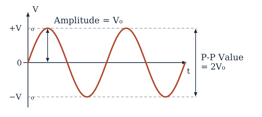
What is the difference between peak to peak and amplitude in case of sine wave?

Amplitude

It is the maximum value of the wave measured from the zero line, that is $V_o$.

Peak to Peak Value

It is measured from the positive peak to the negative peak, so it is twice the amplitude.
$$V_{p-p}=2V_o$$
A single sine wave with its amplitude and its peak-to-peak value marked
SQ 17.4

Why are RC-circuits used in timing circuits?

RC in timing circuits

A capacitor charges and discharges through a resistor at a rate fixed by the time constant, which is a known and repeatable delay.
$$\tau=RC$$

Control

Choosing the values of $R$ and $C$ sets that delay, so the circuit switches after a predictable time.
SQ 17.5

Why are choke coils preferred over resistors for limiting current in AC circuits?

Choke to limit current

A choke limits the current by its reactance rather than by resistance.
$$X_L=2\pi fL$$
The current lags the voltage by nearly $90^{\circ}$, so its power factor is almost zero and no power is wasted as heat.

Comparison

A resistor limiting the same current would dissipate $I^2R$ as heat and would need cooling.
SQ 17.6

Define rms values of voltage and current with their phasor diagrams.

Rms Values

The rms value is the value of the steady current or voltage that produces the same power in a resistor as the alternating one.
$$I_{rms}=0.707\,I_o$$
$$V_{rms}=0.707\,V_o$$

Phasor Diagram

Each is drawn as an anticlockwise rotating vector along the direction of its peak-value phasor, with a length of $0.707$ of it.
CRQ 17.1

What do you mean by rating of electrical appliances? Explain briefly.

Rating of an Appliance

It is the set of values marked on an appliance, its working voltage, power and frequency, at which the maker has designed it to run safely.

Use of the Rating

The current and the resistance follow from it, so a 1 kW heater on a 250 V supply draws 4 A and must not be put on a higher voltage.
$$I=\frac{P}{V}$$
CRQ 17.2

The energy stored in an inductor is analogous to the kinetic energy of a moving mass? Justify.

Energy in inductor

Yes. The energy of an inductor depends on the square of the current, just as the kinetic energy of a body depends on the square of its speed.
$$U_m=\frac{1}{2}LI^2$$
$$K.E.=\frac{1}{2}mv^2$$

Analogy

Inductance $L$ plays the part of the mass and the current $I$ the part of the velocity, so an inductor opposes a change of current as a mass opposes a change of velocity.
CRQ 17.3

What are safety measures to take when working with AC or DC?

Safety Measures

Switch the supply off and confirm with a tester before touching any circuit.
Use insulated tools, keep the hands dry and stand on a dry insulating floor.
Earth every metal casing and fit fuses or circuit breakers of the correct rating.
Discharge the capacitors of a DC circuit before handling it, and never work on a live line alone.

Extra Care with AC

AC of the same magnitude is more dangerous than DC, because its reversals make the muscles grip the conductor and it can throw the heart into fibrillation.
CRQ 17.4

How does self-induction manifest when a current is switched on or off in a circuit?

When Switched On

The growing current induces a back emf which opposes the rise, so the current takes some time to reach its final value instead of jumping to it.

When Switched Off

The collapsing current induces a large emf in the same direction as the original current, which keeps it flowing for an instant and shows itself as a spark at the switch.
CRQ 17.5

Is it possible to achieve mutual inductance using a combination of four coils? If yes, justify your answer.

Mutual induction in four coils

Yes, it is possible.

Justification

Mutual inductance appears between any pair of coils whose changing flux links the other, so four coils give six such pairs. Connecting them in series or in parallel, and setting their spacing and orientation, gives the total mutual inductance required.
CRQ 17.6

The currents of the order of 0.1 A through human body is fatal what causes death; heating due to current or something else?

Cause of Death

Not the heating. A current of this order through the chest throws the heart into ventricular fibrillation, so it stops pumping blood and death follows within minutes.

Role of Heating

Heating burns the skin and the tissue only at much larger currents. A current of 0.1 A is far too small to raise the body temperature dangerously.
MCQ 17.1

Name of device that is used as a part of charging circuit for mobile phones is:

Afull-wave bridge rectifierBhalf-wave rectifier
CAC generatorDbattery
Solution:A charger has to turn the AC of the mains into DC, and the four-diode bridge does it for both half cycles.
MCQ 17.2

A 10 $\mathrm{\mu}$F capacitor is plugged into a 110 V$_{rms}$, 60 Hz voltage source, with an ammeter in series. The value of $I_{rms}$ that passes through the capacitor is:

A0.0415 AB0.415 A
C415 AD0.0415 mA
Solution:Here $X_C=1/2\pi fC=265\,\mathrm{\Omega}$, so $I_{rms}=110/265=0.415\,\mathrm{A}$.
MCQ 17.3

In an RC-circuit, a 10 k$\mathrm{\Omega}$ resistance is connected in series to a capacitor of 0.05 $\mathrm{\mu}$F. The applied voltage for charging is 36 V, the RC-time constant to charge a capacitor is:

A0.0578 msB0.009 ms
C0.500 msD5.49 ms
Solution:The time constant is $\tau=RC=10^4\times0.05\times10^{-6}=5\times10^{-4}\,\mathrm{s}$, and the applied voltage does not enter it.
MCQ 17.4

In a purely inductive or capacitive circuit, the average power consumed is:

Aequal to apparent powerBminimum
CmaximumDzero
Solution:The phase difference is $90^{\circ}$, so $\cos\theta=0$ and the element returns all the energy it stores.
MCQ 17.5

Through which of the AC-circuit elements both emf and current are in phase?

AresistanceBinductor
CcapacitorDLED
Solution:In a resistor the current follows Ohm’s law at every instant, so both pass their peaks together.
MCQ 17.6

If magnetic field is doubled in an inductor, then, magnetic energy density becomes:

A6 timesBhalf
C4 timesDconstant
Solution:The energy density is $B^2/2\mu_o$, which varies as the square of the field.
MCQ 17.7

RC-time constant is measured in:

AohmBhenry
CvoltDsecond
Solution:The product of ohm and farad is the second, which is why $RC$ is used as a delay.
MCQ 17.8

The magnitude of mutual inductance M between two coils when current changes at 20 A s$^{-1}$ in one coil induces an emf of 50 mV in the other is:

A5 mHB2.5 mH
C0.0025 $\mathrm{\mu}$HD25 mH
Solution:Here $M=\varepsilon_s/(\Delta I_p/\Delta t)=50\times10^{-3}/20=2.5\times10^{-3}\,\mathrm{H}$.
Numerical 17.1

AC circuit configure by a resistance of 20 $\mathrm{\Omega}$, capacitor of capacitance 40 $\mathrm{\mu}$F is connected to an AC supply of 110 V having frequency 50 Hz. Calculate: (a) capacitive reactance (b) current in the circuits (c) suggest phase between the voltage and current in a capacitive circuit. (Ans: (a) 79.58 $\mathrm{\Omega}$ (b) 1.34 A (c) current leads voltage by 75.9$^{\circ}$)

Given Data

$$R=20\,\mathrm{\Omega}$$
$$C=40\,\mathrm{\mu F}=40\times10^{-6}\,\mathrm{F}$$
$$V_{rms}=110\,\mathrm{V}$$
$$f=50\,\mathrm{Hz}$$

To Find

Reactance $X_C=?$, current $I_{rms}=?$ and phase angle $\theta=?$

Formula

$$X_C=\frac{1}{2\pi fC}$$
$$Z=\sqrt{R^2+X_C^2}$$
$$I_{rms}=\frac{V_{rms}}{Z}$$
$$\theta=\tan^{-1}\left(\frac{X_C}{R}\right)$$

Solution

The capacitive reactance is
$$\begin{aligned}X_C&=\frac{1}{2\times3.14\times50\times40\times10^{-6}} \\ &=79.58\,\mathrm{\Omega}\end{aligned}$$
The impedance of the series circuit is
$$Z=\sqrt{(20)^2+(79.58)^2}=82.06\,\mathrm{\Omega}$$
$$\begin{aligned}I_{rms}&=\frac{110\,\mathrm{V}}{82.06\,\mathrm{\Omega}} \\ &=1.34\,\mathrm{A}\end{aligned}$$
The phase angle is
$$\begin{aligned}\theta&=\tan^{-1}\left(\frac{79.58}{20}\right)=\tan^{-1}(3.979) \\ &=75.9^{\circ}\end{aligned}$$

Result

$$X_C=79.58\,\mathrm{\Omega}$$
$$I_{rms}=1.34\,\mathrm{A}$$
The current leads the voltage by $75.9^{\circ}$.
Numerical 17.2

An alternating current I is represented by the equation; $I=420\sin(100\pi t)$. Find: (a) the rms current (b) the frequency. (Ans: (a) 296.94 A (b) 50 Hz)

Given Data

Comparing with $I=I_o\sin\omega t$
$$I_o=420\,\mathrm{A}$$
$$\omega=100\pi\,\mathrm{rad\,s^{-1}}$$

To Find

Rms current $I_{rms}=?$ and frequency $f=?$

Formula

$$I_{rms}=0.707\,I_o$$
$$\omega=2\pi f$$
$$f=\frac{\omega}{2\pi}$$

Solution

The rms value of the current is
$$I_{rms}=0.707\times420=296.94\,\mathrm{A}$$
The frequency is
$$f=\frac{100\pi}{2\pi}=50\,\mathrm{Hz}$$

Result

$$I_{rms}=296.94\,\mathrm{A}$$
$$f=50\,\mathrm{Hz}$$
Numerical 17.3

A 50 Hz AC of peak value 1 A flows through primary coil of a transformer. If the mutual inductance between the primary and secondary be 1.5 H, then find the mean value of induced voltage. (Ans: 300 V)

Given Data

$$f=50\,\mathrm{Hz}$$
$$I_o=1\,\mathrm{A}$$
$$M=1.5\,\mathrm{H}$$

To Find

Mean induced voltage $\varepsilon_s=?$

Formula

The current rises from zero to its peak in a quarter of a period.
$$T=\frac{1}{f}$$
$$\Delta t=\frac{T}{4}$$
$$\varepsilon_s=M\frac{\Delta I_p}{\Delta t}$$

Solution

The time taken is
$$\Delta t=\frac{1}{4\times50\,\mathrm{Hz}}=0.005\,\mathrm{s}$$
So the rate of change of the primary current is
$$\begin{aligned}\frac{\Delta I_p}{\Delta t}&=\frac{1\,\mathrm{A}}{0.005\,\mathrm{s}} \\ &=200\,\mathrm{A\,s^{-1}}\end{aligned}$$
$$\begin{aligned}\varepsilon_s&=1.5\,\mathrm{H}\times200\,\mathrm{A\,s^{-1}} \\ &=300\,\mathrm{V}\end{aligned}$$

Result

$$\varepsilon_s=300\,\mathrm{V}$$
Numerical 17.4

A 220 V AC source of frequency 2 kHz is connected across a capacitor of 10 $\mathrm{\mu}$F. Find out: (a) the reactance $X_C$ of capacitor (b) the current in the circuit. (Ans: (a) 7.96 $\mathrm{\Omega}$ (b) 27.63 A)

Given Data

$$V_{rms}=220\,\mathrm{V}$$
$$f=2\,\mathrm{kHz}=2000\,\mathrm{Hz}$$
$$C=10\,\mathrm{\mu F}=10\times10^{-6}\,\mathrm{F}$$

To Find

Reactance $X_C=?$ and current $I_{rms}=?$

Formula

$$X_C=\frac{1}{2\pi fC}$$
$$I_{rms}=\frac{V_{rms}}{X_C}$$

Solution

The capacitive reactance is
$$\begin{aligned}X_C&=\frac{1}{2\times3.14\times2000\times10\times10^{-6}} \\ &=7.96\,\mathrm{\Omega}\end{aligned}$$
The circuit has only the capacitor, so the current is
$$\begin{aligned}I_{rms}&=\frac{220\,\mathrm{V}}{7.96\,\mathrm{\Omega}} \\ &=27.63\,\mathrm{A}\end{aligned}$$

Result

$$X_C=7.96\,\mathrm{\Omega}$$
$$I_{rms}=27.63\,\mathrm{A}$$
Numerical 17.5

In a coil of inductance 150 mH, a current changes steadily from 50 mA to 30 mA in 164 ms, find: (a) the magnitude (b) direction of induced emf. (Ans: (a) 18.29 mV (b) same direction as the original current)

Given Data

$$L=150\,\mathrm{mH}=0.15\,\mathrm{H}$$
$$\Delta I=30-50=-20\,\mathrm{mA}$$
$$\Delta t=164\,\mathrm{ms}=0.164\,\mathrm{s}$$

To Find

Induced emf $\varepsilon_L=?$ and its direction

Formula

$$\varepsilon_L=-L\frac{\Delta I}{\Delta t}$$

Solution

Putting the values in the formula
$$\begin{aligned}\varepsilon_L&=-0.15\,\mathrm{H}\times\frac{-20\times10^{-3}\,\mathrm{A}}{0.164\,\mathrm{s}} \\ &=0.01829\,\mathrm{V}\end{aligned}$$

Result

$$\varepsilon_L=18.29\,\mathrm{mV}$$
The current is falling, so the induced emf acts in the same direction as the original current and opposes the decrease.
Numerical 17.6

A choke coil is needed to operate a lamp at 160 V$_{rms}$ and 50 Hz. The lamp has a resistance of 5 $\mathrm{\Omega}$ when running at 10 A$_{rms}$. Calculate the inductance of the choke coil. (Ans: 48.4 mH)

Given Data

$$V_{rms}=160\,\mathrm{V}$$
$$f=50\,\mathrm{Hz}$$
$$R=5\,\mathrm{\Omega}$$
$$I_{rms}=10\,\mathrm{A}$$

To Find

Inductance of the choke $L=?$

Formula

The choke and the lamp are in series, so
$$V_R=I_{rms}R$$
$$V_L=\sqrt{V_{rms}^2-V_R^2}$$
$$X_L=\frac{V_L}{I_{rms}}$$
$$L=\frac{X_L}{2\pi f}$$

Solution

The voltage across the lamp is
$$V_R=10\,\mathrm{A}\times5\,\mathrm{\Omega}=50\,\mathrm{V}$$
So the choke must drop
$$V_L=\sqrt{(160)^2-(50)^2}=151.99\,\mathrm{V}$$
$$X_L=\frac{151.99\,\mathrm{V}}{10\,\mathrm{A}}=15.2\,\mathrm{\Omega}$$
$$\begin{aligned}L&=\frac{15.2\,\mathrm{\Omega}}{2\times3.14\times50\,\mathrm{Hz}} \\ &=0.0484\,\mathrm{H}\end{aligned}$$

Result

$$L=0.0484\,\mathrm{H}=48.4\,\mathrm{mH}$$

Self Test

Seventeen questions across the whole chapter. Work through them without the notes, then check the answers keyed at the foot of the page.

Q 1

An alternating voltage is given by $V=311\sin(314t)$. Its rms value is nearly:

A155 VB220 V
C311 VD440 V
Q 2

An alternating current reverses its direction 100 times in one second. Its frequency is:

A100 HzB50 Hz
C200 HzD25 Hz
Q 3

An alternating quantity stays at its peak value for:

Aone half of the cycleBa quarter of the cycle
Can instant onlyDthe whole cycle
Q 4

If the peak power dissipated in a resistive load is 1 kW, its mean power is:

A250 WB500 W
C1 kWD2 kW
Q 5

The phase difference between the current and the voltage of a choke coil is nearly:

A$0^{\circ}$B$45^{\circ}$
C$90^{\circ}$D$180^{\circ}$
Q 6

Which one of the following consumes no power in an AC circuit?

Aa resistorBa pure capacitor
Ca filament lampDan electric heater
Q 7

The reactance of a 1 H inductor at a frequency of 100 Hz is nearly:

A100 $\mathrm{\Omega}$B314 $\mathrm{\Omega}$
C628 $\mathrm{\Omega}$D1000 $\mathrm{\Omega}$
Q 8

Doubling the frequency of the supply across a capacitor makes the current through it:

Aone halfBdouble
CunchangedDfour times
Q 9

In which of the following circuits is the impedance equal to the resistance?

Aan RC-series circuitBan RL-series circuit
Ca purely resistive circuitDa purely inductive circuit
Q 10

A circuit draws 2 A rms from a 220 V rms supply. Its impedance is:

A55 $\mathrm{\Omega}$B110 $\mathrm{\Omega}$
C220 $\mathrm{\Omega}$D440 $\mathrm{\Omega}$
Q 11

In an RL-series circuit $R=3\,\mathrm{\Omega}$ and $X_L=4\,\mathrm{\Omega}$. Its power factor is:

A0.6B0.75
C0.8D1
Q 12

A device which converts alternating current into direct current is called a:

AtransformerBrectifier
CinverterDchoke
Q 13

An inverter does the reverse of a rectifier, that is, it converts:

AAC into DCBDC into AC
CDC into DCDAC into AC
Q 14

If the current through an inductor is doubled, the energy stored in it becomes:

Aone halfBdouble
Cfour timesDunchanged
Q 15

The self-induced emf in a coil is largest when the current through it:

Ais largestBis constant
Cchanges most rapidlyDis zero
Q 16

The mutual inductance of a pair of coils is reduced by:

Aincreasing the number of turnsBwinding them on an iron core
Cmoving the coils farther apartDincreasing their area of cross-section
Q 17

The maximum ripple voltage of a full-wave bridge rectifier is decided by:

Athe number of diodes usedBthe load current and the frequency
Cthe peak input voltageDthe resistance of the diodes

Answers 1 (b)2 (b)3 (c)4 (b)5 (c)6 (b)7 (c)8 (b)9 (c)10 (b)11 (a)12 (b)13 (b)14 (c)15 (c)16 (c)17 (b)